Computing Projects
RC2014 Classic ][
Take a look at the build log if you'd like to see how I put it together.
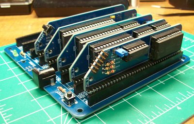
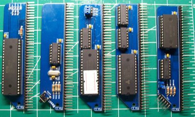
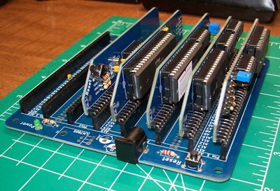
Z80 based modular computer
- 32k RAM with BASIC and SCM
- 6 pin FTDI compatible header
- 8 slot RC2014 Standard Bus backplane
RC2014: First Boot
Introduction
09-January-2025
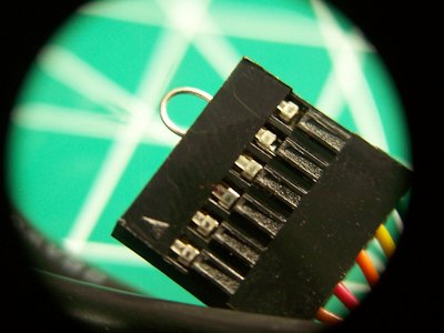
The big day finally arrived! My FTDI cable was waiting in the mailbox when I came home from work and it was time for the first boot of the RC2014 project. After a few minutes of tracking things down in the terminal and adding my user account to the dialout group I fired up puTTY and plugged everything in.
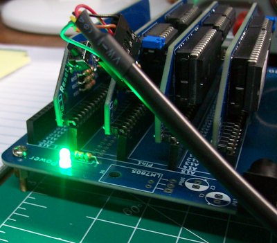
The first good sign appeared when the green LED on the backplane lit up signifying the machine had power! I then set the baud rate, connected to the machine, pressed the reset button and... nothing. I was disappointed but not terribly surprised, after my dodgy repair on the one of the serial board's ICs I had a feeling things weren't going to work.
before going further I did a test of the FTDI cable by bridging the TX and RX lines with a cuttoff and typing into the terminal. I was getting back what I put in just like I should so the cable was working fine.
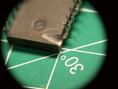
After a little more research I learned that the repaired leg was not ground as previously thought but the vcc line. I was able to measure the voltage with my multimeter and instead of the 5V it should have had, it only showed 2.3V. Time to redo this repair and see if that worked.
To say this step wasn't nerve racking would be a bald-faced lie. Thankfully, even if I completely destroyed the IC a replacement could be had for about $20 on eBay, that discovery put my mind at ease a little. Out came the jeweler's file and the work began. Two episodes of Star Trek later I had exposed enough of the pad to get a bead of solder to stick. Next I prepared another cutoff from a resistor and tinned the end. A drop of flux helped everything to flow together and the new prosthetic was installed!
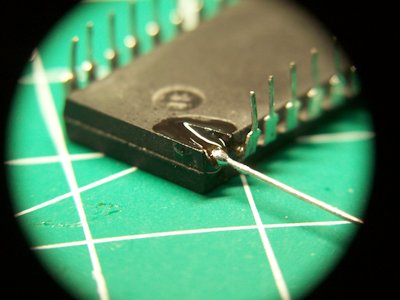
Reinserting the IC to it's socket and checking the voltage revealed a successful repair! The chip was now pulling the full 5V that it expected. I re-slotted the serial board into the backplane and attempted to boot again. Still nothing useful. Occasionally I would get a few lines of garbled output from the machine and I suppose any signs of life are a good thing. I decided to check over all the boards for unseated ICs, of which I found a few. I also searched for cold solder joints, bridged joints, the usual goofs, but found none. Another boot attempt and another blank screen. Not even the reassurance of gibberish this time.
Next Steps
Next on the troubleshooting list is to ensure all components are installed where they're supposed to be, testing ground connections and measuring voltage to both the boards and ICs to see if I can narrow things down further.
Conclusion
While I am disapointed that the machine failed to boot, this experience of successfuly repairing the broken leg was very rewarding. I've never completed such an intricate repair before and I'm rather proud of the final product. besides, if I wanted a computer that didn't require tinkering I wouldn't have purchased one I have to put together. I can't say when I'll finally get it up and running, but I'm sure I'll get there eventually.
[Back to Top]
It Speaks! Kinda...
Introduction
17-January-2026
Today I was able to run some troubleshooting steps on the RC2014 and even managed to eek out a little progress. The following actions were taken in order to get to this point:
- Checked all IC were placed in correct sockets (they were not).
- Identified two misplaced resistors and replaced them on the correct boards (CPU and Clock Modules).
- Attempted connecting with different baud rates in puTTY:
- 115200
- 9600
- 57600
- 38400
- 19200
- Verified 5V and Ground along entire backplane.
- ensure continuity between the clock pin on the Clock Module and the Serial Module.
- Removed socket from Motorola 68B50 and soldered IC directly to the PCB in an attempt to remove potential short (no effect).
Conclusion
Progress has been made and at no small cost. I'm not sure what my next steps will be as I'll need to do a little more research at this time. But it's not lost on me that I've advanced from a blank screen to one with text and that means we've got power and the CPU is trying to do stuff. I may end up needing to buy and assemble a new Serial Module as that is the only area I can fathom the error is occurring at this point.
[Back to Top]
Resistor Swap
18-January-2026
Introduction
Today was another full day of troubleshooting. It may not seem like much but just tracing the grounds and 5V rails took a lot of time. Here is a quick rundown of things checked:
- Confirmed FTDI cable is 5V compliant.
- Checked the VCC and ground connections along the entire backplane.
- Checked VCC and ground between the Serial Board and the corresponding legs on the Z80.
- Pulled every board except the CPU and Serial Modules, checking voltages as I reinstalled each Module.
- Examined every board for cold joints and solder-hairs.
- Reflowed suspicious joints with fresh solder.
- Confirmed clock activity with multimeter.
- Confirmed data traffic on CPU with multimeter.
- Ensured that reset switches were oriented properly.
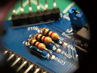
After all this it was time to hit the forums. I found that many users had experienced an issue with the supplied resistors on the TX and RX lines of the Serial Module where they caused too great a limit on the signal which conflicted with some FTDI cables. Since I couldn't think of anything else, I decided to give it a try.
The Swap
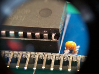
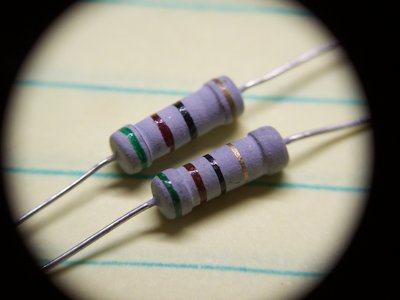
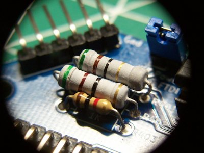
From what I could tell, most people chose to swap the supplied 1kΩ resistors for 470kΩ or 330Ω resistors. However, I didn;t have any in my parts bin so I decided to wing it and put on some 51Ωs I did have.
Conclusion
A wise man once told me "Pessimists are always right, but optimists make money." Well I'm usually right (and broke) so I guess it's true. Anyway, my hopes weren't high for the swap to do anything and I turned out to be right this time too. Thankfully, this little experiment didn't cause any of the magic smoke to leak out either.
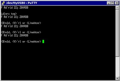
After two days of working on the machine I'm right back where I started. The computer will boot and connect with the terminal but the output is just garbled noise. I did notice that on one line the characters include "z80" which I'm taking as a sign that the system is actually attempting to boot.
I'm really not sure where to go from here. Without a logic probe or oscilloscope there's not much more I can do in the way of troubleshooting and I've already promised myself I'd upgrade my multimeter before investing in any other tools. So, on the shelf it goes, at least for a little while until I can come back to it a little older, a little wiser, and with fresh eyes.
[Back to Top]
Toshiba NB-205
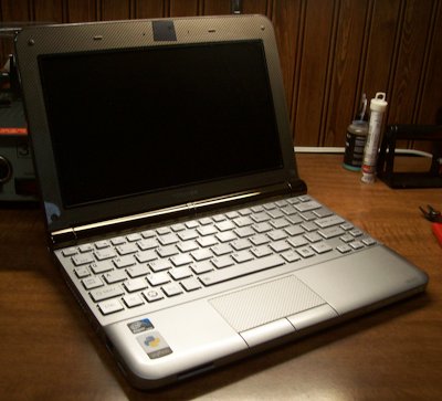

The Toshiba NB-205 is a netbook computer released in North America in 2009 and even at the time it was considered an entry-level machine. Packaged with a single gigabyte of DDR3 RAM, a 250GB HDD (hurray for platters!) and running the novel Intel Atom N280 @ 1667 GHz. With a 1024x600, 10 inch LCD display the netbook boasts an impressively usable keyboard and with the extended (Ni-Cad) battery can run for 6-8 hours on a full charge.
So why would I willing run a (at the time of writing) SIXTEEN YEAR OLD laptop? And a budget netbook at that? Simple, I like it. The compact size was a major selling point for me back in the day and it still make an impact in the thought process today. In addition, this little pizza-box boasts three USB-A ports, a VGA out, SD slot, full-size Ethernet port, a microphone jack and (GASP) a headphone jack. For a tinkerer like me, the compact size and all those ports matter, a lot.
The Toshiba NB-205 is my primary laptop for day-to-day and hobby use. That's not to say it's my only laptop. Even after upgrading the RAM browsing the web is sluggish even in browsers built to run on old hardware. Upgrading the HDD to a modern SSD allows local programs to run very responsively.
Along with the hardware upgrades (which consisted of roughly $30 worth of parts 10 years ago) I also ditched Windows for Debian 11. This brings us to probably the biggest limitation of the machine. The Atom processor is 32-Bit which is beyond a doubt obsolete. This makes finding software impossible for Windows and difficult for Linux. That's not to say it's impossible, as you'll see from the screenshots, this little laptop is still capable of doing some serious work.
Screenshots

Running the Chicago95 theme on top of XFCE really makes things feel right on this machine.
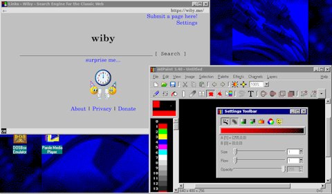
I can still edit images for this website locally using mtPaint and the Links2 browser makes reading articles online a breeze.
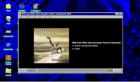
The single, tiny speaker on the netbook sounded terrible when it was new and is nearly useless after years of use. However, the headphone jack still works like a charm!
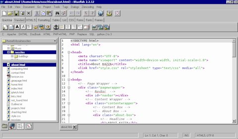
Bluefish Editor might not have a dark mode but it works like a charm!
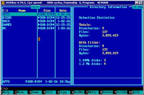
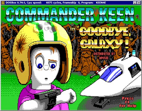
By utilizing the DOSbox emulator I can run a plethora of classic games and even productivity software like WordStar.
Conclusion
So at the end of the day, should you get an old netbook to use as a daily driver? Probably not. Troublshooting and making repairs on obsolete hardware is a hobby for me and I would not want to need to rely on the NB-205 for my job or coding large projects. But for updating this website, checking my email and tinkering around it's a blast!
A few words of advice if this article has got you wanting to explore older hardware:
- Get something with a 64-bit processor.
- Look for something built for industry.
- Ensure parts availability.
- If you don't already, learn to enjoy fixing things.
While the 32-bit processor in this Toshiba still gets the job done, it presents an ever growing list of complications and limits on software.
ThinkPads have a reputation for reliability and repaibility that is unmatched. If I had to to it all again (and I very well might in the near future) I'd be looking for a ThinkPad on eBay.
This goes in hand with point 2, if you're going to play with obsolete hardware you need to make sure a replacement battery isn't going to cost you more than you paid for the machine in the first place.
It may go without saying but working on these old machines is a lot like working on old cars, you're going to spend more time inside the guts than behind the wheel. but that's all a part of the hobby in my opinion and most of the fun in using obsolete hardware is the opportunity to really learn the machine inside and out.
Thermal Pads
If you enjoyed this write-up you'll probably also like the entry on my project page where I took the whole thing apart to replace the thermal pads
[Back to Top]
Pi-Star Config.
Introduction
12-January-2026
In this article I'll be covering the provisioning and deployment of my DMR hotspot using an MMDVM board and Raspberry Pi 3B+. The process took a whole afternoon so I won't bore you with all the nitty gritty details or in-depth troubleshooting, just the highlights.
Step 1: Flashing the SD Card
This was a large part of the time investment on this endeavor, surpassed only by the process of dialing in the offset. This shouldn't have taken as long as it did as I've don't this before in previous Pi projects. It's simple really, download the OS image, flash it to an SD car, and boot. I did this about three or four times on different computers wit different software before I finally decided try a different SD card and realized I had been using a 2GB card the whole time! this was the source of my troubles as these OS images really like to have 10GB or more. Once I swapped to a correctly sized SD things went as expected
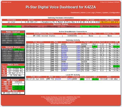
Once I could access the dashboard it was time to enter all the settings. This is where I'm editing out a lot of time on this write-up. It was entirely a matter of following various youtube guides and entering the information required in the configuration page, not very exciting.
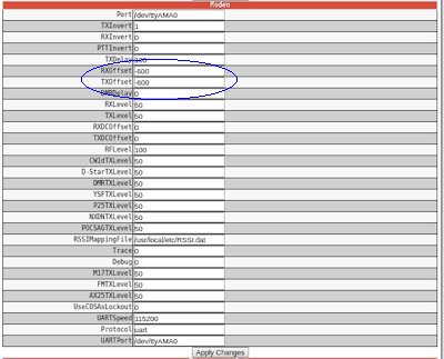
Step 2: Troubleshooting
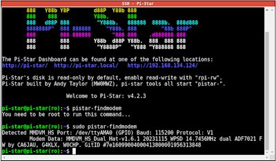
Once all the configuration info was entered I though we'd be off to the races but when is it ever that simple? Every time I tried to connect to the hotspot I'd get a busy signal and show no local traffic on the dashboard. The first thing to do was ensure that the Pi could even see the MMDVM hat. To do this was a simple matter of using SSH within Pi-Star to talk to the Pi and check if it could identify the hat. Once that was established I attempted using different drivers and experimenting with different offset values for TX and RX. Eventually, through trial and error, I found that an offset of -600Mhz allowed the radio and the hat to communicate! Once that was complete I added a few talkgroups to the codeplug (which took a little trial and error itself), programmed the radio and I was off to the races!
Conclusion
This was honestly a bit more frustrating of an experience than I expected but once I was able to key-up into the World Wide talkgroup and hear accents from Indonesia and Australia in shack it was all worth it. Considering the setup and troubleshooting would have been just as necessary with a prebuilt device I'm happy I went this rout and could have the added enjoyment of knowing I put the whole thing together myself.
I'm excited to get more involved with DMR and making contacts. When I limited myself to the Technician license I thought international contacts would be out of reach until I could upgrade to General. Thanks to this little device I'm able to really reach out and talk to HAMs from all over the globe and that's pretty cool.
[Back to Top]