<--- Return to Projects Page
Build Log: RC2014 Classic ][
Introduction
This is an exciting project and one I've been looking forward to for a while now. Designed to mimic the micro computing kits from the late 70s and built around the venerable z80 processor. While this build was complex, the included instruction from Z80kits.com were incredibly clear and helpful. You'll see that I had a few mishaps along the way and I'll go into more detail about how I handled those when we get to them. This entry will only cover the assembly process, if you'd like to see how things went with the first boot head over to the computing page for a full rundown.
Step 1: Parts and Pieces
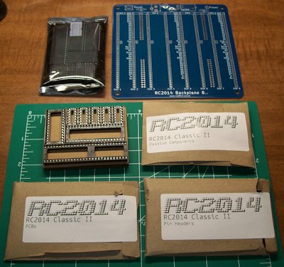
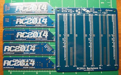
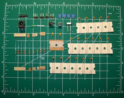
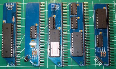
The kit came very well packaged and organized. the ICs were stored in their own little envelope and static free bag. The PCBs were all have clearly printed silkscreens telling you what every module is and where each component goes.
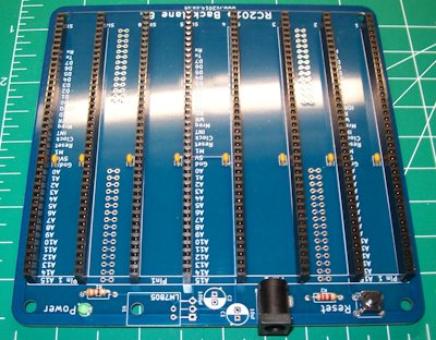
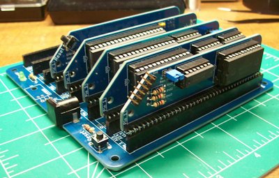
Step 2: Putting it all Together
Judging by the photos everything seems to have gone together smoothly, though that's not entirely how things happened. I must say, the difficulties I experienced were not the fault of the kit but completely self-inflicted. For starters, when my good solder ran dry I hastily ran to the nearest Walmart to pick up a new tube and my goodness is this stuff terrible. If I did it all over again I would have waited the few days it would have taken for some good solder to arrive from Amazon. The cheap lead-free solder caused a few issues but it really boogered up one of the pins on the CPU board (more on that later).
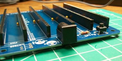
You'll also notice in one of the images that I have placed a piece of electrical tape over the 5V barrel-jack. This is because I intend on providing power via the FTDI cable at first and using a wall-wart in combination can cause the magic smoke to leak out. YIKES!
Step 3: Goofs and Mishaps
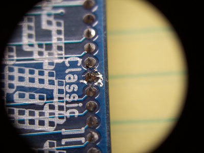
I'm not too proud to admit when I've made a boneheaded move, mostly because that would leave me with terribly little to talk about. As stated earlier I made the mistake of using cheap solder. In the photo below you'll see the ugly mess it made of one of the pins on the CPU socket. While I don't think there is any damage that will impact booting it sure does look nasty.
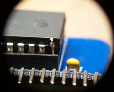
Later, while attempting to install one of the ICs on the Serial board I hsd s catastrophic failure and snapped a leg right off the IC! Thankfully, there seemed to be enough material to solder on the cutoff from another component in it's place. While I did successfully check for continuity between the leg and socket, only attempting to boot will tell if my prosthetic fix worked or if I'll have to purchase a new IC.
NOTE: The macro images used here were taken using my newly acquired "macro lense" harvested from an old RCA camcorder.
Step 4: Completed Computer
With it all soldered together I gave everything a bath in 91% isopropyl alcohol to remove the leftover flux from the PCBs and put it all together. the eagle eyed among you may notice that the modules are installed incorrectly in the photos, after revisting the instructions I may sure to get everything in the correct sockets.
Conclusion
Blunders aside, this was a remarkably rewarding build. Sadly, I am still awaiting the delivery of a Serial cable before I can attempt the first boot. That adventure will be covered in full on the Computing page when the day comes.
<--- Return to Projects Page